 Once upon a time,
long long ago
and far far away,
in a magical land,
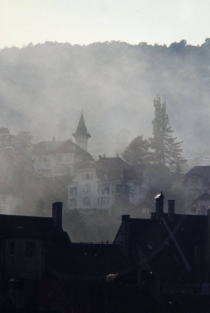
called Switzerland,
|
Once upon a time,
long long ago and far far away, in a magical land, called Switzerland, |
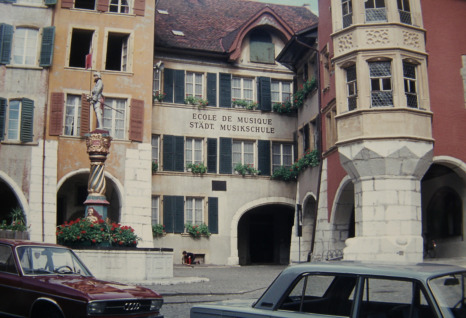
in the beautiful old town of Biel, or Bienne in french - it's completely bilingual - there lived |
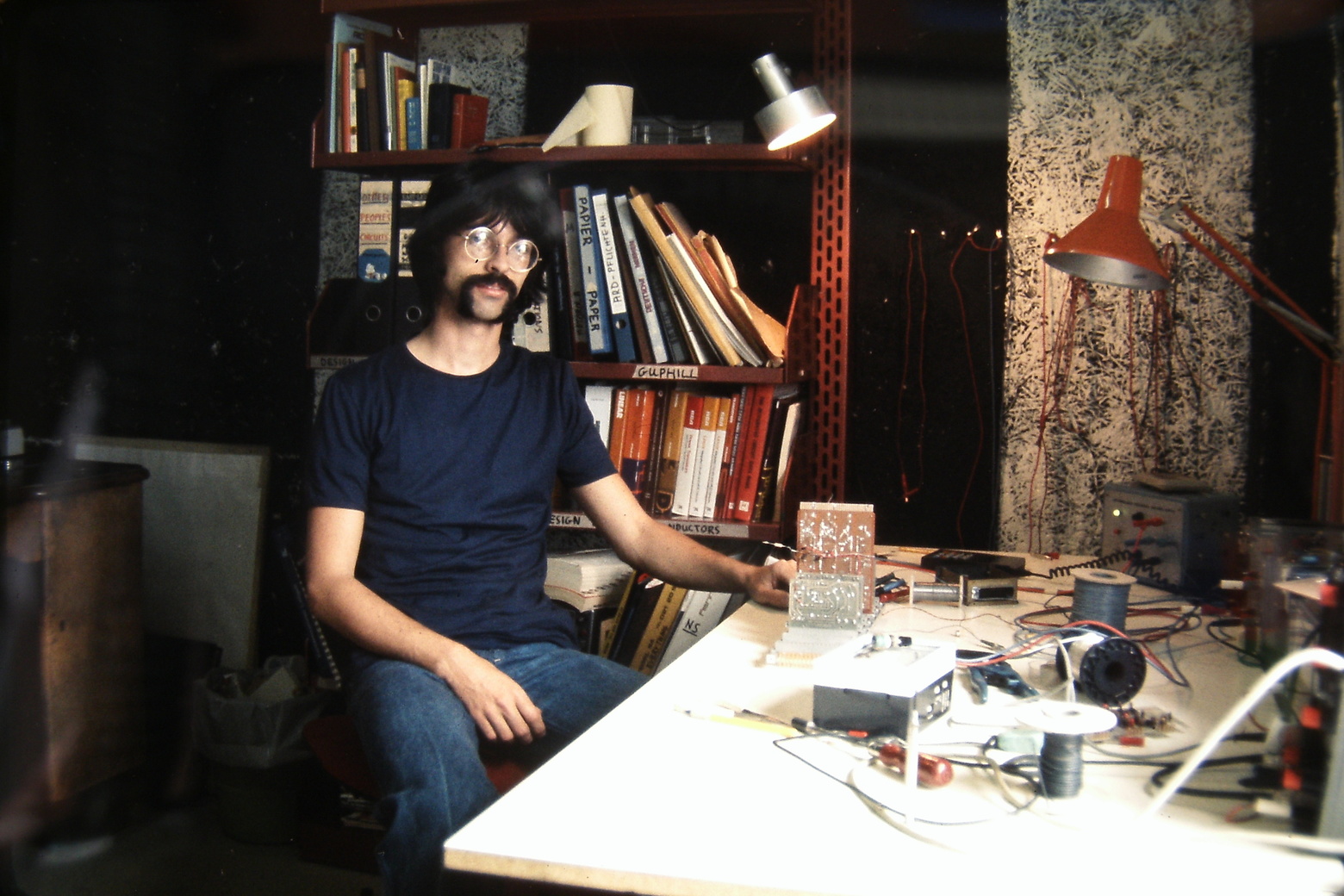
a young electronic engineer, |
 who worked for a firm called Filtek, and designed audio electronics
for the German radio and TV broadcast studio market,
including developing the circuitry,
who worked for a firm called Filtek, and designed audio electronics
for the German radio and TV broadcast studio market,
including developing the circuitry,
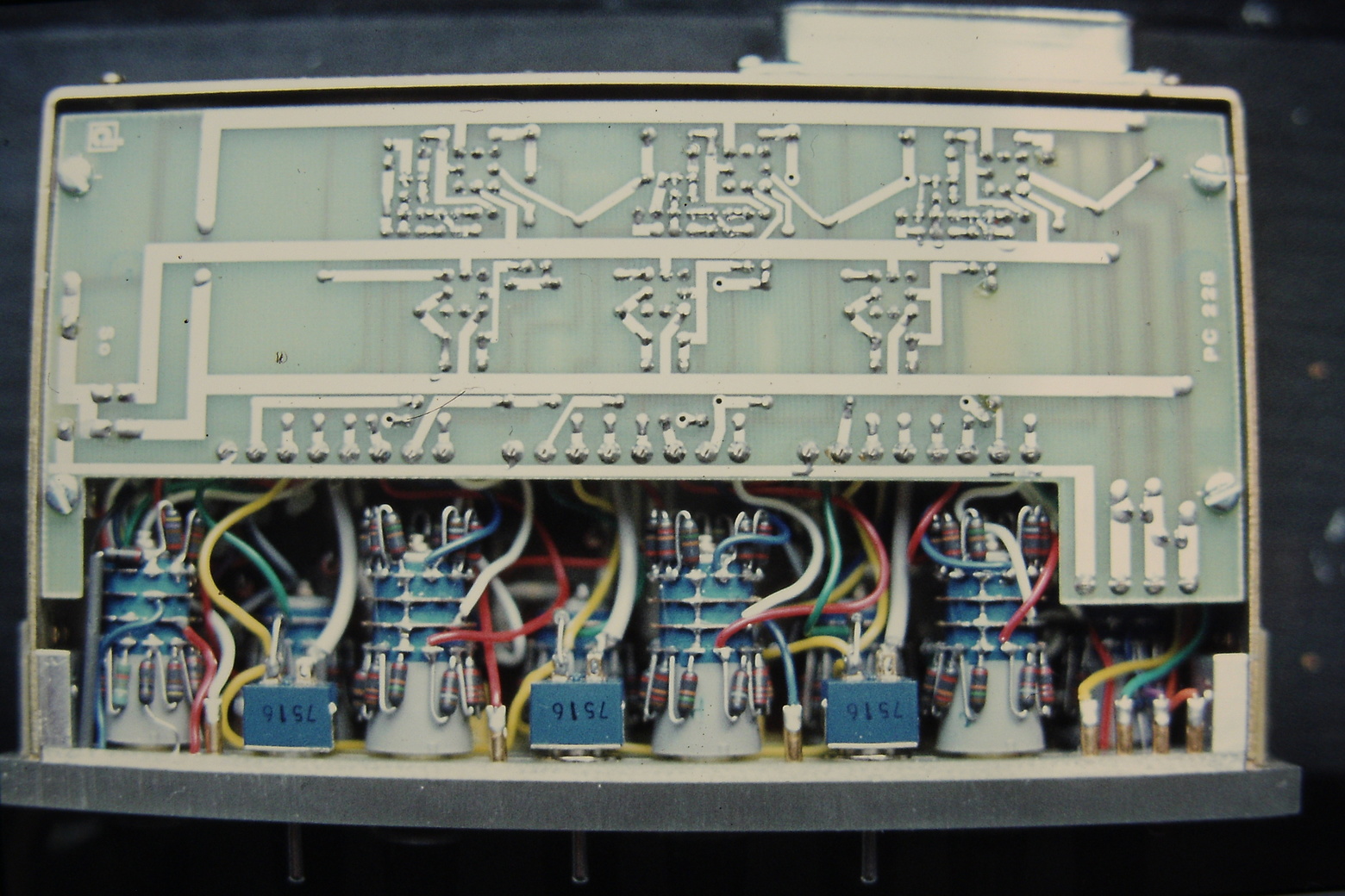
but also laying out the printed-circuit boards and designing the front panels. |
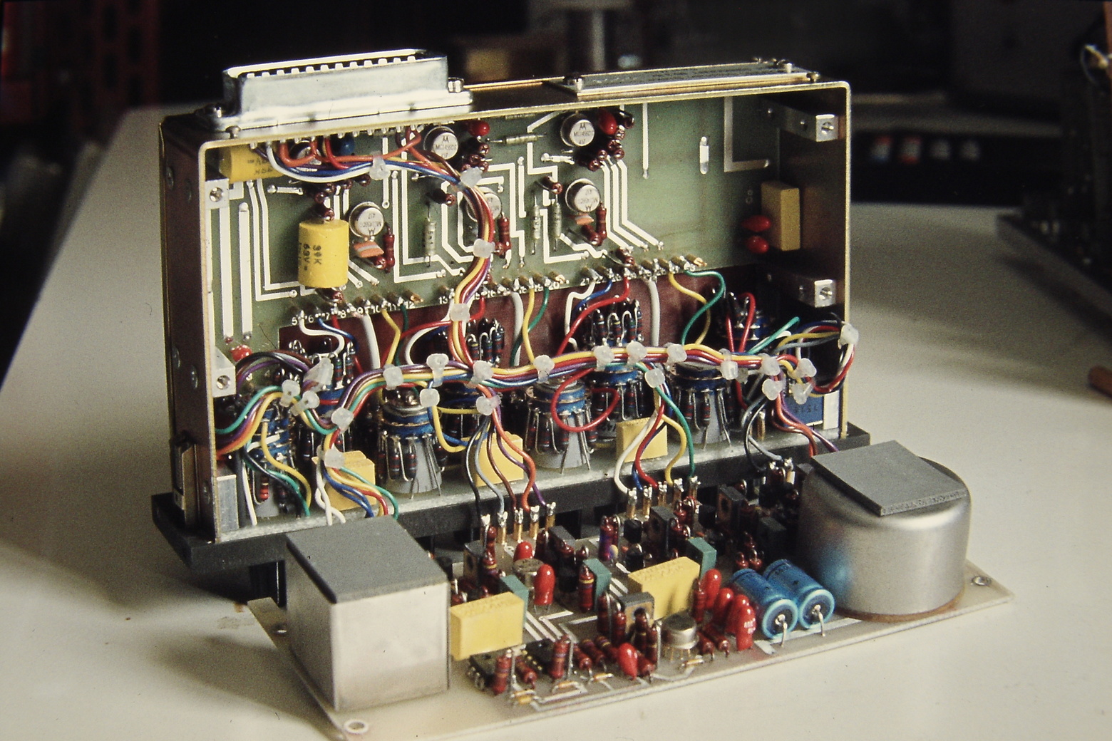
 In that market, the mixing desks were built up of pluggable modules,
which were very strictly specified and all intercompatible,
electrically and mechanically.
In that market, the mixing desks were built up of pluggable modules,
which were very strictly specified and all intercompatible,
electrically and mechanically.
The desks, and the rest of the studios, were built by Telefunken and Siemens. |
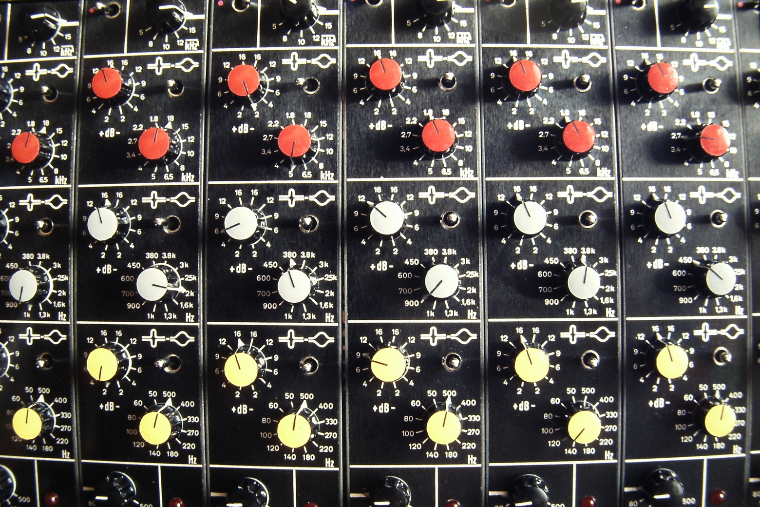
So Filtek made replacement filter, compressor, expander, and fader modules - drop-in replacements for the Telefunken and Siemens originals, |
 but with more modern circuitry,
and lots more knobs on the front panel.
but with more modern circuitry,
and lots more knobs on the front panel.
|
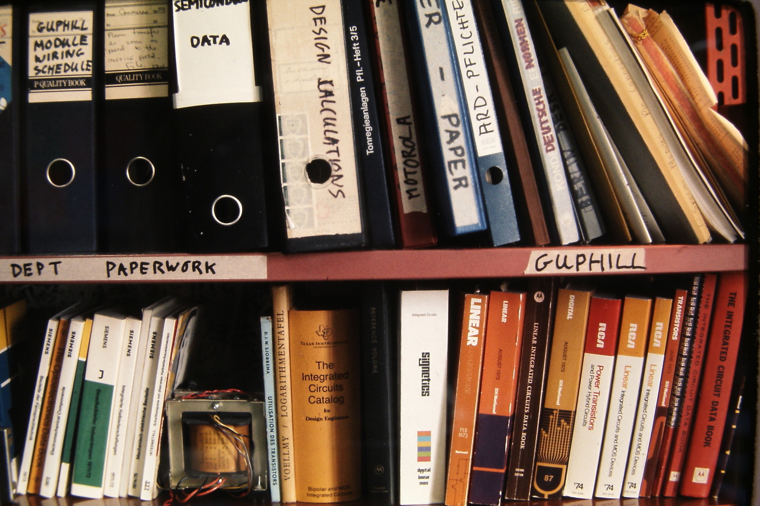
His bookshelf was full of books and papers, |
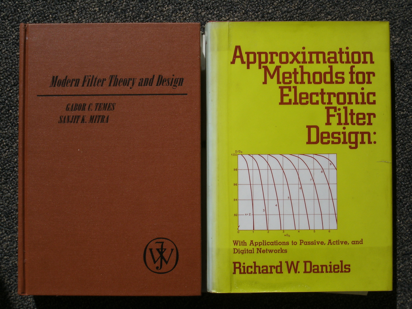 including some classics of filter theory:
Temes and Mitra (1973), and Daniels (1974)
including some classics of filter theory:
Temes and Mitra (1973), and Daniels (1974)
|
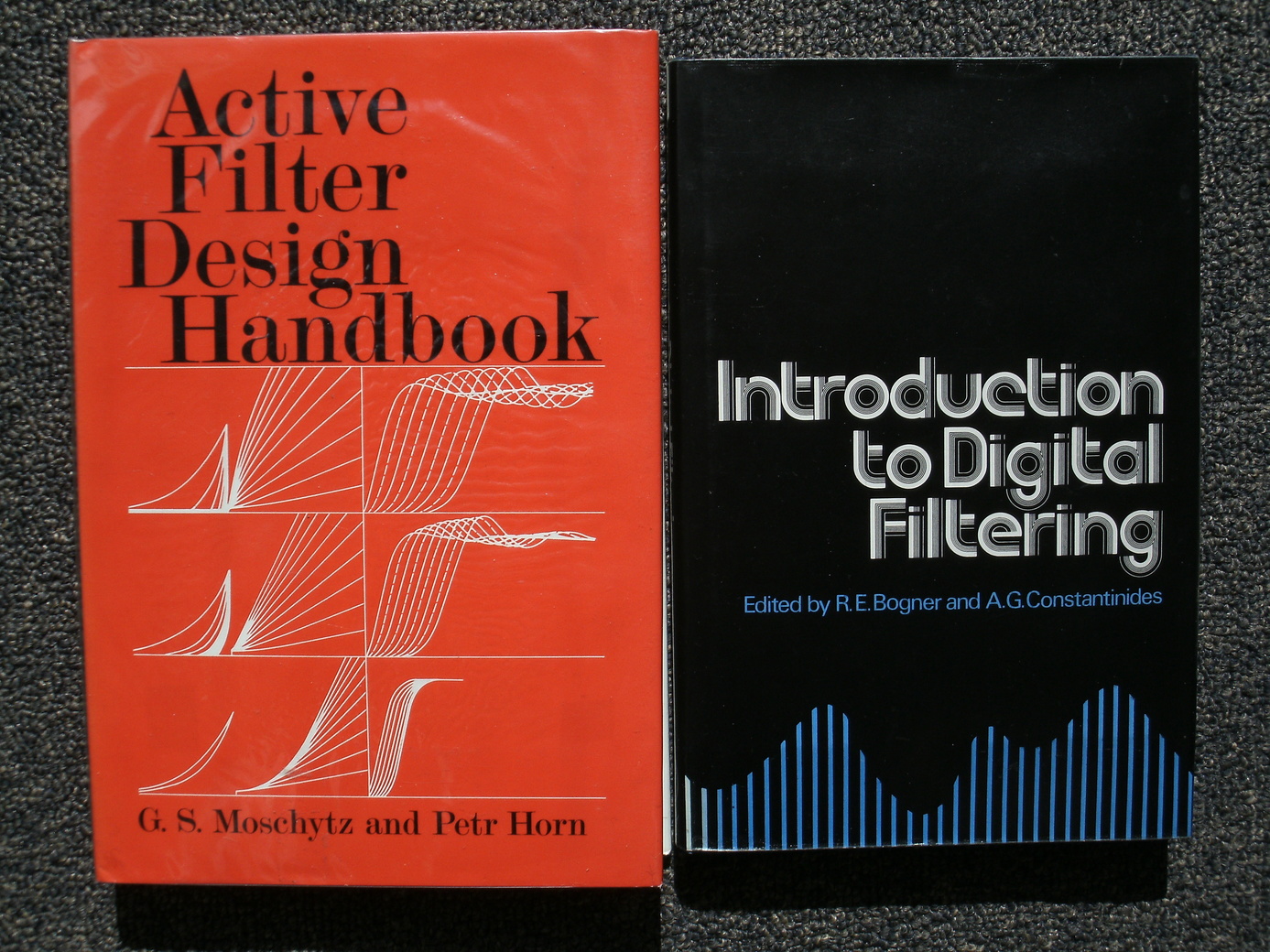 and Moschytz and Horn (1981).
I used these books a great deal.
and Moschytz and Horn (1981).
I used these books a great deal.
The book on the right, Introduction to Digital Filtering, by Bogner and Constantinides, I found more confusing. But we never needed it at the time, and I only made a serious attempt to understand it forty years later, in July 2017. |
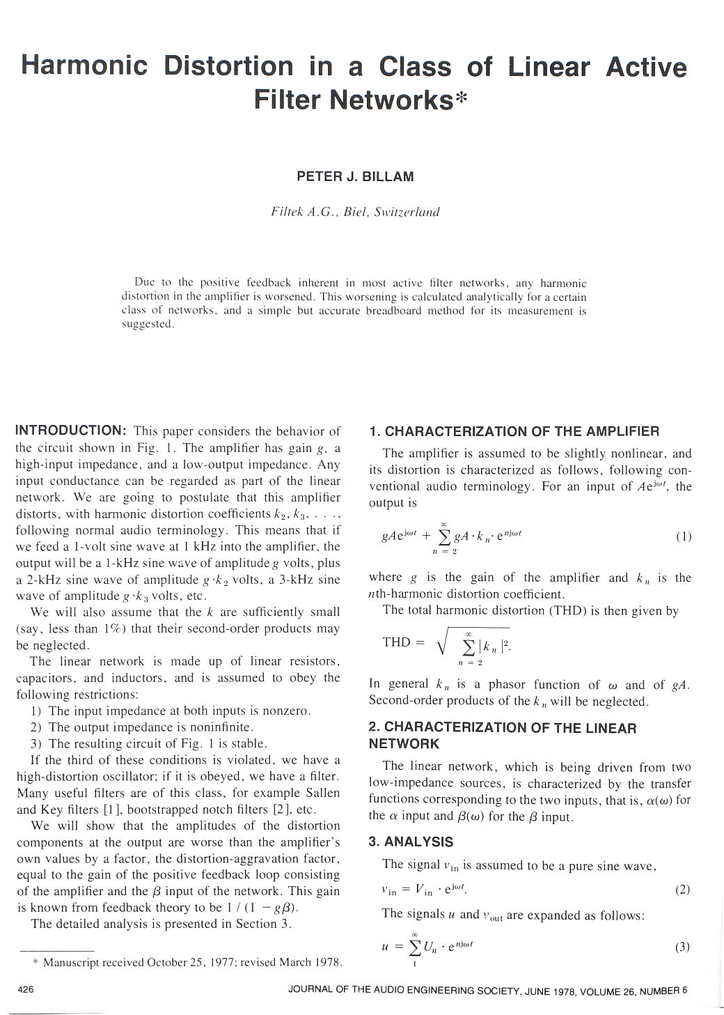
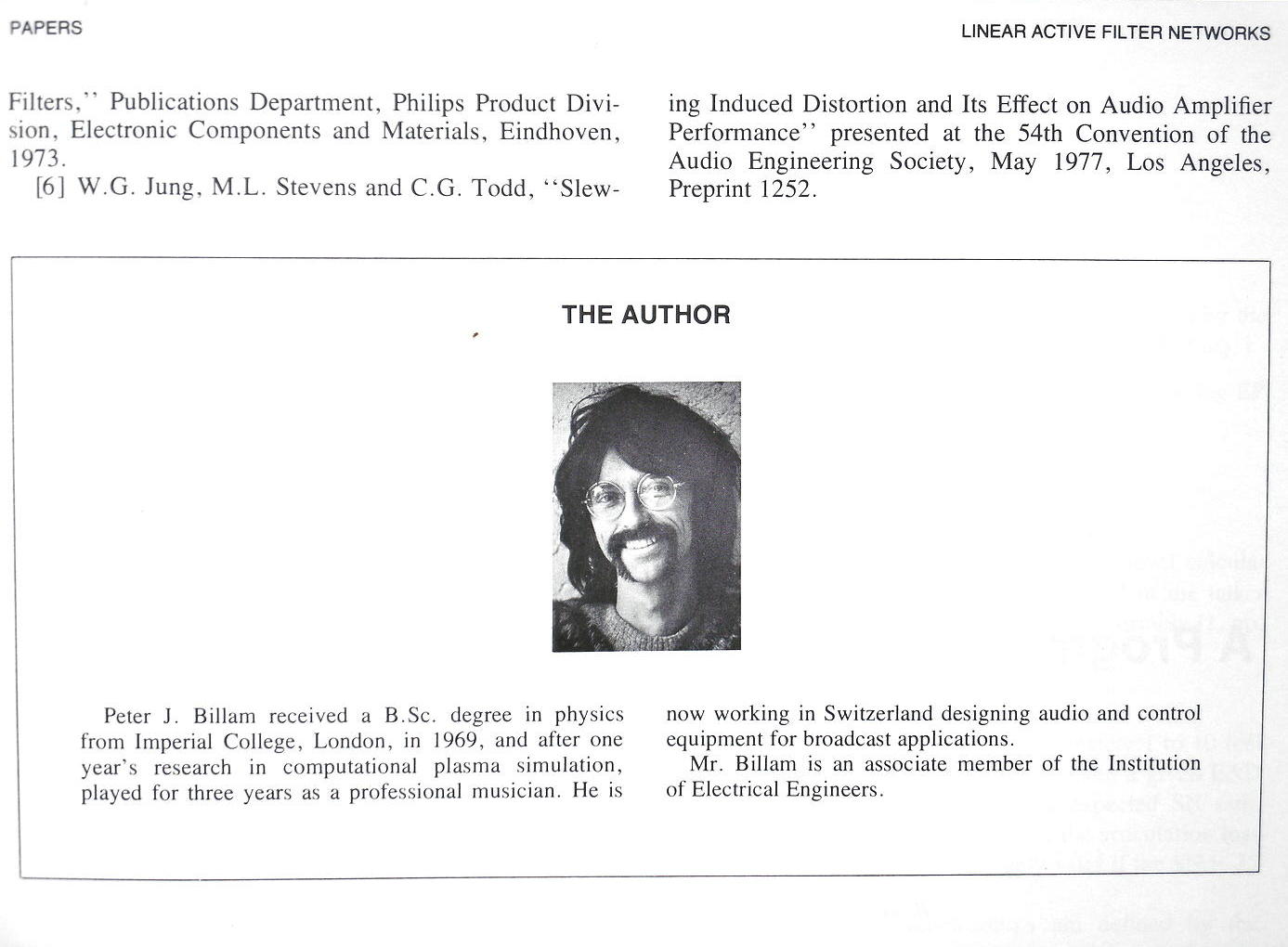
In analog filters I became very fluent, and even published two papers in learned journals. The first of these, for the JAES, is good, and launched a whole field of study, though the second, for the IEEE, is seriously flawed. Both are available on-line at peterbillam.fastmail.com.user.fm/comp/ |
|
|
|
|

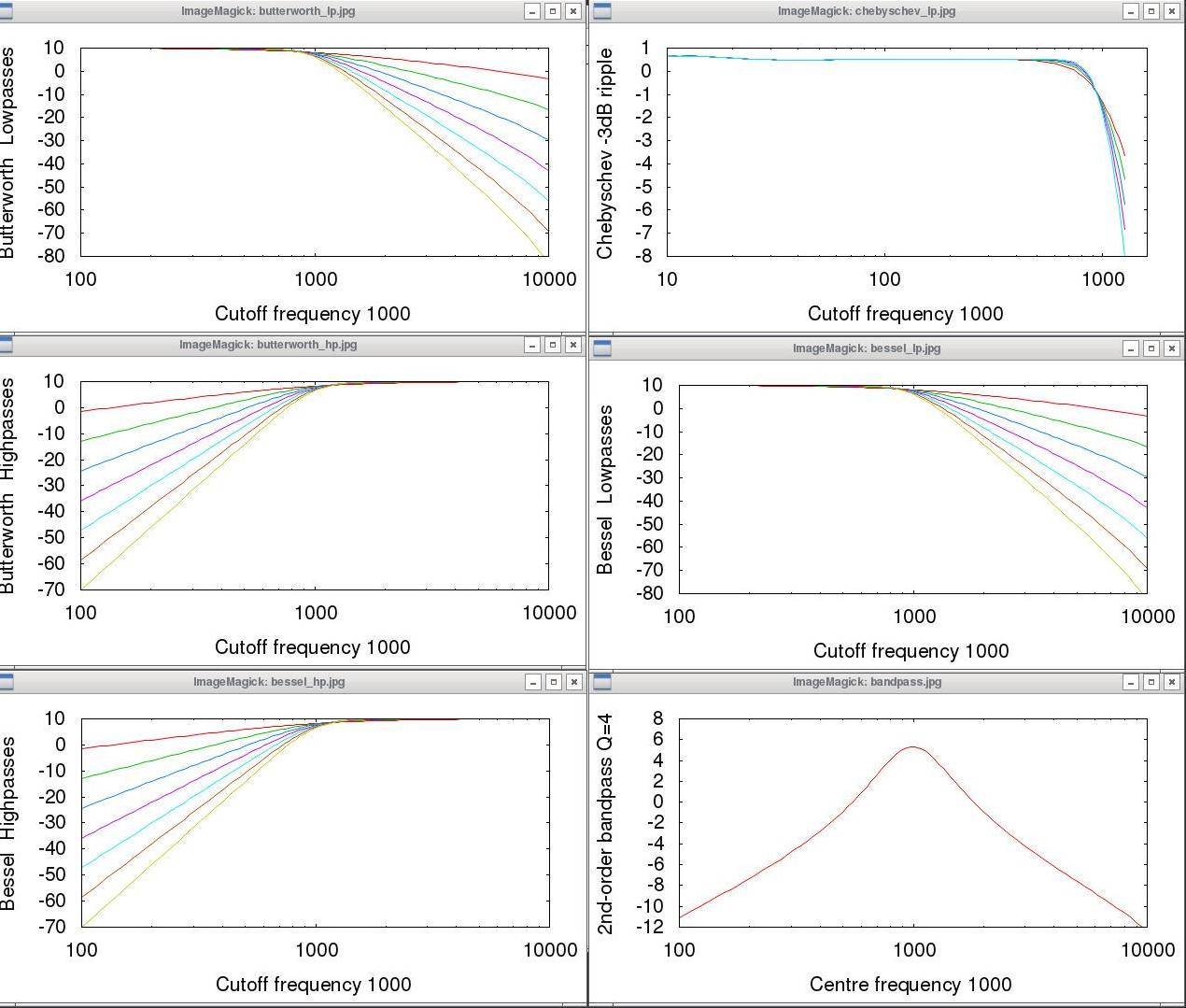
Different polynomials give different frequency-responses.
|
|
|
So I thought: why not generate ten white noises, filter the first at 20Kz, the second at 10Khz, the third at 5Kz and so on in octaves all the way down, then mix them in some proportion ? It's an approximation, but it should be realistic . . . So I decided to investigate Digital Filters again. |
|
Digital filters work numerically,
on regularly sampled data,
like audio data at 44100 samples per second,
or scientific data at any other rate.
|
|
The previous sample is z-1, the one before that is z-2, the current sample is z0, the next sample is z+1, and so on. So instead of a Fourier Transform to the frequency domain, digital filter theory works with a z-1 transform to the z domain. |
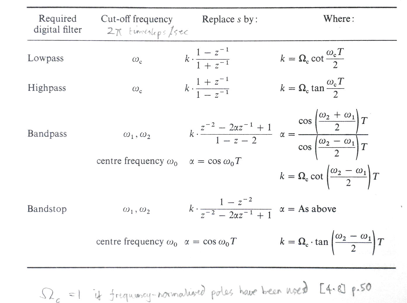 Much of the theory concerns converting the desired frequency-response
from its frequency-domain,
into the parameters you need to multiply the time-samples
in the z-1 domain.
Much of the theory concerns converting the desired frequency-response
from its frequency-domain,
into the parameters you need to multiply the time-samples
in the z-1 domain.
1) find the normalised frequency-domain poles for a lowpass filter with cut-off frequency=1 2) then convert the Laplace transform to its equivalent z-1 transform 3) and calculate the numerator to morph the lowpass into your desired shape, and denormalise it to the desired cut-off frequency. See Rorabaugh pp.151, 156, 189 and Constantinides p.56 |
|
To quote en.wikipedia.org/wiki/Digital_filter ; "The design of digital filters is a deceptively complex topic. Although filters are easily understood and calculated, the practical challenges of their design and implementation are significant and are the subject of much advanced research."
In the literature I have, the notation is often confusing. For example,
in Temes/Mitra p.152 the general z-1 transfer-function is
given with parameters A2 in the numerator equal to zero.
|
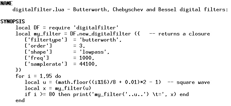 The digitalfilter module
API offers only one function:
new_digitalfilter(),
which takes only one argument:
a table of the options that specify the filter.
The digitalfilter module
API offers only one function:
new_digitalfilter(),
which takes only one argument:
a table of the options that specify the filter.
new_digitalfilter() returns a closure, which is the filter-function that you then call, once per timestep, and which stores all its internal state: the options, and the recent input and output values that it needs. |
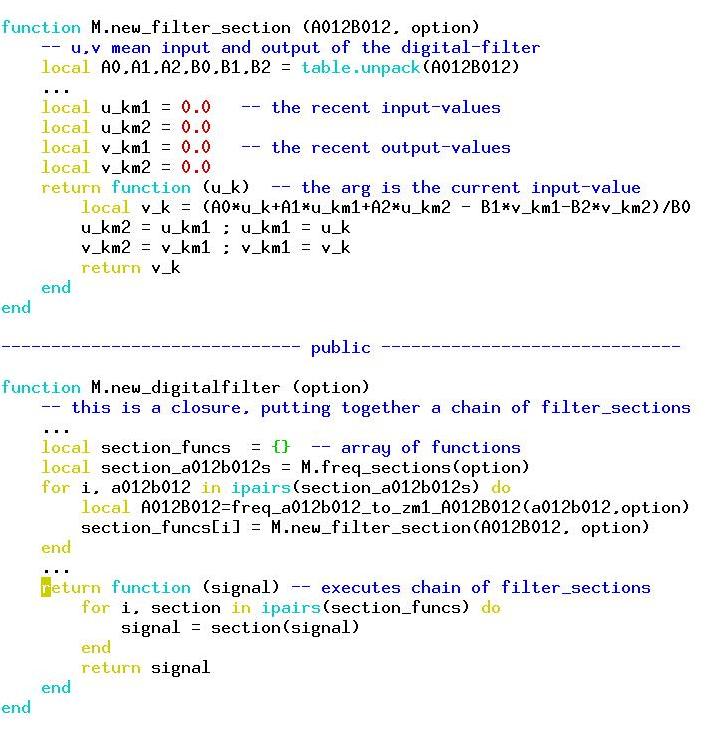 This is a very highly redacted version of the key bits of the code . . .
The function you call from the API is new_digitalfilter() (below) It first puts together an array of functions which implements the second-order sections that will make up your desired filter. It then returns the closure function that you will use to convert each input-sample to its output-sample. To generate its array of section-functions, it first calls freq_sections() to turn your desired filter into an array (section_a012b012s) of the a0, a1, a2, b0, b1, b2 coefficients that implement your filter in the frequency domain. Then it calls freq_a012b012_to_zm1_A012B012() to convert those into the equivalent coefficients in the z-1 domain. Then it calls new_filter_section() (above) to generate a function which does the calculation, remembering those recent input- and output-values it needs. |
 We'll have a quick look at freq_a012b012_to_zm1_A012B012
It unpacks the array argument into six scalar variables, does the complex arithmetic of the conversion (the imaginary parts cancel out :-) and returns an array of the equivalent coefficients in the z-1 domain. |
To Do
|
The tests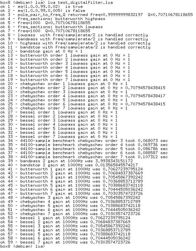
|
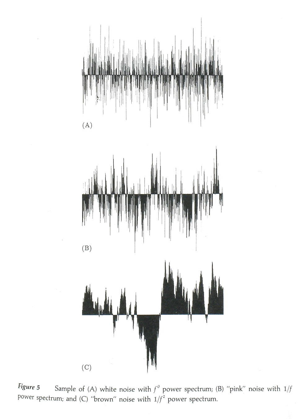
My pink noise generator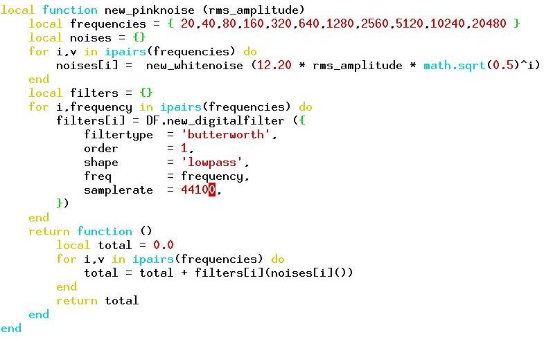
listen to the mp3 . . . (first white, then pink, then red noise) |
"Digital Filter Designer's Handbook",
C. Bitton Rorabaugh, TAB Books (McGraw-Hill)
cdn.preterhuman.net/texts/engineering/Dsp/
peterbillam.fastmail.com.user.fm/comp/free/digital_filter_designers_handbook_1.pdf
peterbillam.fastmail.com.user.fm/comp/lua/digitalfilter.html
peterbillam.fastmail.com.user.fm/comp/lua/digitalfilter_talk/index.html
peterbillam.fastmail.com.user.fm/comp/index.html#electronics
"Modern Filter Theory and Design",
Gabor C. Temes and Sanjit K. Mitra,
Wiley, 1973
"Approximation Methods for Electronic Filter Design",
Richard W. Daniels,
McGraw-Hill, 1974
"Introduction to Digital Filtering",
R.E. Bogner and A.G. Constantinides,
Wiley, 1975
"Active Filter Design Handbook",
G.S. Moschytz and Petr Horn,
Wiley, 1981
en.wikipedia.org/wiki/Fourier_transform
en.wikipedia.org/wiki/Laplace_transform
en.wikipedia.org/wiki/Digital_filter
en.wikipedia.org/wiki/Butterworth_filter
en.wikipedia.org/wiki/Chebyshev_filter
en.wikipedia.org/wiki/Bessel_function
en.wikipedia.org/wiki/Bessel_polynomials
en.wikipedia.org/wiki/Bessel_filter
en.wikipedia.org/wiki/Bessel_filter#Digital
en.wikipedia.org/wiki/Pink_noise
www-users.cs.york.ac.uk/~fisher/mkfilter/trad.html
www-users.cs.york.ac.uk/~fisher/mkfilter/mzt.html
www.dsprelated.com
aptitude show octave-signal
sox -n -d synth pinknoise
peterbillam.fastmail.com.user.fm
And, finally, a word from our sponsor at the JAES . . . |
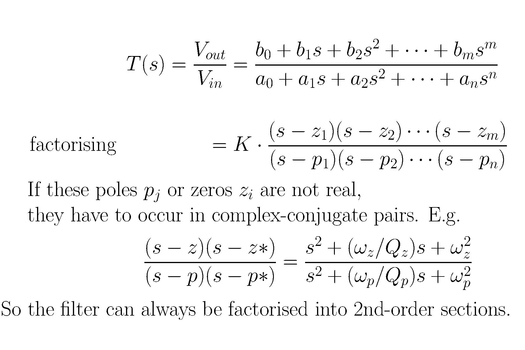 Starting from the n-th order differential equation of the network,
applying the Laplace transform,
we get the Transfer Function T(s)
as the ratio of two polynomials.
Starting from the n-th order differential equation of the network,
applying the Laplace transform,
we get the Transfer Function T(s)
as the ratio of two polynomials.
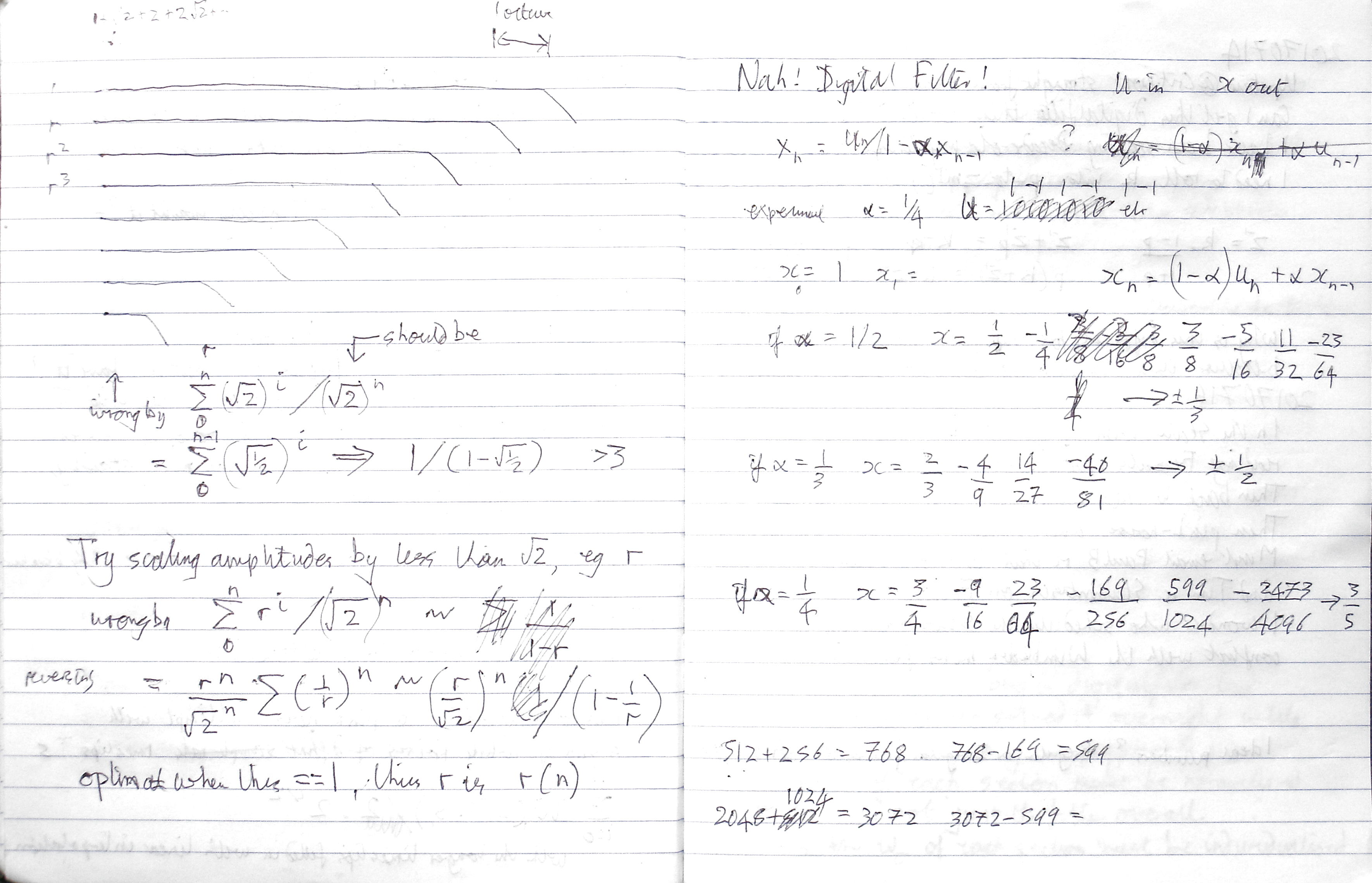
 Then forty years later, in July 2017,
I got an idea for synthesising Pink Noise . . .
Then forty years later, in July 2017,
I got an idea for synthesising Pink Noise . . .